How to Prevent Condensation in Radiant Cooling Applications?
How to Prevent Condensation in Radiant Cooling Applications?
Radiant Cooling reduces air ducting size by 75-90%, maximizes ceiling height and improves indoor air quality. Tips for preventing condensation in cooling mode in Commercial, Residential and Institutional Buildings.
Introduction
Conventional Forced Air Heating and Cooling Systems, are non passive mechanically driven systems that have been widely used across North America for decades following the post second war era. Such systems offers multiple advantages (such as scalability, economy of scale, adaptability to small and large buildings, etc... ) and disadvantages (such as high first cost, sound level, poor energy efficiency, high maintenance cost, leakages, dirt accumulation in ducts, etc...).
With today's more stringent energy efficiency building's codes, climate change and increased people awareness, trend is reversing toward more passive heating and cooling systems using renewable or semi-renewable energy sources (Such as Solar, Geothermal, Air to Water Heat Pumps, etc...).

When properly designed and installed, Hydronic Radiant Cooling and Heating Systems can passively change the temperature felt by human's body to the desired comfortable level without the need to blow air all over the livable indoor space.
Pumping liquid into the infloor loops (or even capillary tubes installed in walls and ceilings) costs less than blowing air since liquid is an incompressible flow while air is not, and the amount of thermal energy (heat or cold) that can be transported by a unit volume of Liquid is higher than the one of Air.
Sound level of fluid flowing through infloor loops is zero, while sound level through air grilles, chilled beams, registers, etc... is never zero.
The result of the above is a more uniform temperature across conditioned indoor space, a zero sound level which definitely lead to a higher thermal comfort and a better occupants satisfaction.
Further Readings:
To know more about radiant cooling, how to generate chilled water in residential projects and what equipment available for residential radiant cooling applications, please go through the below blogs:
How do Heating, Cooling, Dehumidification and Humidification Works?

Ambient Air is a mixture of dry air and water vapor. Thermal Comfort is established when Air Temperature and the % of Water Vapor contained in the surrounding air (Expressed in either absolute or relative humidity) are brought up to a desired level (called thermal comfort).
Heating is a one stage process: it simply increases the temperature of ambient air, in a passive (such as infloor heating, capillary tubes, sun light infiltration, etc...) or non passive mechanically driven method (such as forced air heating, etc...). Adding Water Vapor to Heated Air is called Humidification. When Air is heated, its relative humidity decreases and humidification process usually follows heating process. Humidity is generated by devices such as steam, evaporative, ultrasound, etc.... humidifiers.
Unlike Heating, Cooling is a 2 stages process:
- Dry Cooling is the process of Cooling Air without reducing the % of water vapor contents in the air (we call it sensible cooling). Like Heating, cooling can be passive (radiant cooling, etc...) and non passive (Forced air, Natural Ventilation, etc...).
- Dehumidification or Latent Cooling is the process of reducing the % of water vapor in the ambient air, by exposing air to a cooling medium at a temperature lower than its dew point temperature.
in Places like Canada and Northern US States, Sensible Cooling Load represent between 75-90% of Total Cooling Load, and Latent Cooling Load represents the remaining 10-25% of Total Cooling Load. Radiant Cooling through either floor, walls or ceiling should always be a dry cooling process, since dehumidification on either floor, walls or ceiling surfaces is not desired in a livable space.
By implementing radiant cooling into any HVAC projects, we can reduce forced air ducting system size and cost by 75-90% and eliminate air born and duct born noise. Reducing Duct Sizes by 75-90% means having indoor space with higher ceiling, more natural light and better overall occupant satisfaction. For Radiant Cooling to cover a significant % of Total Cooling Load, the following prerequisites have to be met:
- Flooring R value shall be kept as low as possible, since radiant floor cooling energy output increases when thermal resistance of cooled surface decreases. Bare Concrete floor (with possible epoxy finish) is the ideal scenario since it has an R value of 0. Ceramic Tile or Stone Floor has an R value of 0.5 and Hard Wood Floor (3/4" Thick) has an R value close to 1.
- Building's Envelope shall be designed, in Collaboration between Architect and Mechanical Engineer, for the Nominal Sensible Cooling Demand (Load) divided by the Building Area to be kept as small as possible (between 6-10 Btu/hr/ft²).
- For a 75°F (23°C) Indoor Temperature and 50% Relative Humidity, Indoor Air Dew point Temperature is 55.13°F (12.85°C). To avoid Condensation on floor, floor top surface's temperature shall be kept above the ambient air dew point temperature.
- To Maximize Cooling Energy output of the floor, infloor pipes shall be as close as possible (the minimum is 6 inches center to center spacing). The bigger the cooling load requirements or the higher the flooring thermal resistance is, the smaller is infloor pipes spacing.
Radiant Cooling Energy Output per unit area of floor Vs Chilled Water Mean Supply Temperature (for Various Flooring Thermal Resistance R Values) - for 6 inches spacing between infloor pipes

Suitable Chilled Water Supply/Return Temperatures to prevent condensation
To determine the required supply and return chilled water temperatures for infloor cooling loops, we need to understand the link between infloor loops spacing, Flooring overall Thermal Resistance and Sensible Cooling Load

Thermal Resistance of Flooring depends on Type, Thickness, Covering, etc.... Below is a table of the most common flooring type as well as their most common thermal resistance (Always confirm with manufacturer about thermal resistance, they vary from one brand to another):
| Type of Flooring | Thickness (in) | R Value (Btu/hr.ft².°F) |
|---|---|---|
| Carpeting | 1/8 | 0.6 |
| 1/4 | 1.0 | |
| 1/2 | 2.0 | |
| 3/4 | 3.0 | |
| 1 | 4.0 | |
| Urethane Pad | 1/4 | 1.0 |
| 1/2 | 2.0 | |
| Rubber Pad | 1/4 | 0.4 |
| 1/2 | 0.8 | |
| Vinyl or Lino | 1/8 | 0.2 |
| Ceramic Tile or Stone | 1/8 | 0.2 |
| 1/4 | 0.4 | |
| 1/2 | 0.8 | |
| Hardwood | 1/4 | 0.3 |
| 1/2 | 0.6 | |
| 3/4 | 0.9 | |
| Softwood | 1/4 | 0.4 |
| 1/2 | 0.8 | |
| 3/4 | 1.2 | |
| 1 | 1.6 |
The higher the floor thermal resistance, the colder water circulating in loops should be to have the same cooling flow through the cooled surface. Also the closer infloor pipes to each others, the higher is the cooling flow. Below Graphs show Cooling Energy Output (per unit area of floor) V/s Loops Mean Chilled Water Temperature for 6 inches pipes spacings center to center:

6" spaced infloor loops Sensible Cooling Capacities Vs Mean Water Temperature Chart
Ex: for a Hardwood Flooring with a thermal resistance close to 1 and a mean chilled water temperature of 55°F (50.5°F Supply and 59.5°F Return), the sensible cooling capacity of the floor is 7.2 Btu/hr for every square foot (ft²) of area.
By pumping chilled water at lower temperature of 50°F (45.5°F Supply and 55.5°F Return), the sensible cooling capacity of the floor becomes 9 Btu/hr for every square foot (ft²) of area.
Sensible Cooling Capacity increases with flooring having lower thermal resistances.

6" spaced infloor loops Mean Surface Temperature Vs Mean Water Temperature Chart
Floor Surface Temperature decreases when chilled water temperature decreases.
In all radiant cooling applications, Mean Surface Temperature of the floor shall be at least 5.4°F (3°C) above ambient air dew point temperature. This is avoid having water vapor condensation on the floor surface. An indoor air at 75°F (23°C) Temperature and 50% Relative Humidity has a Dew point Temperature of 55.13°F (12.85°C). In this example, Floor surface temperature is either 69°F (20.55°C) or 70°F (21.11°C) which 13.87°F (7.7°C) above dew point temperature
How Does a Residential Radiant Cooling Design Looks like?
For the radiant cooling design to be cost effective, Sensible Cooling Load Demand shall never be higher than the radiant floor cooling output. When this condition is met, ducting is only required for dehumidification in summer and humidification in winter.

In traditional forced air heat and cooling system, ducting is required to blow hot air in winter and chilled air in summer, however it does not offer the same comfort as infloor heating in winter, especially in cold climates such as Canadian climate. When customers decide to do infloor heating, infloor radiant cooling shall be considered since same infloor loops used for space heating in winter can be used in the summer for dry cooling (by simply pumping chilled water into the infloor loops).
Since dehumidification load, represents between 10-25% in a residential building, doing sensible cooling by the floor will reduce ductworks size by 75-90% as well as cost and noise associated with them.
How can we prevent condensation on a cooled surface (Floor, Radiant Panel in wall or ceiling) in real life?
Automatic Method
There is two automatic ways of resetting chilled water supply temperature versus dew point temperature of ambient air in a way to keep the surface temperature of cooled surface (either floor, wall panel or ceiling panel) few degrees above dew point temperature.
The first automatic method, is to use a mixing valve (s), between supply and return chilled water (or chilled glycol) lines. This mixing valve gradually opens the by-pass, mixes returned chilled water at 60°F (15.55°C) with chilled water coming from the storage tank at 44.6°F (7°C). Mixed chilled fluid temperature will bet at a temprature higher than 44.6°F (7°C) and lower than 60°F (15.55°C).
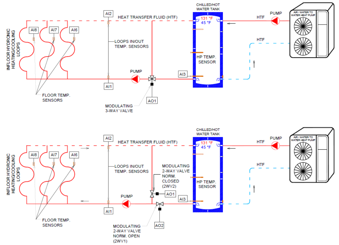

TDPR-01 Controller measures both cooled surfaces temperatures (via multiple temperature sensors) as well as the dew point temperature of the ambient air and reset the supply temperature of the chilled water to maintain 5 degrees Fahrenheit (2.78 degrees Celsius) safety margin between cooled surface and ambient air dew point temperature.
TDPR-01 allows for measuring three different temperatures for three different surfaces having each a unique thermal resistance.
Controller measures the supply and return temperature of the chilled water (or chilled fluid) and modulates the opening
and closing of either the 3-way valve by-pass or 2-way valves (2WV1 and 2WV2) to maintain cooled surface
temperature at 5°F (2.78°C) above the ambient air’s dew point temperature.
Controller can also measure the temperature of the thermal storage tank. When temperature in the tank is above 20°C
(68°F), dew point temperature reset is automatically turned OFF by the controller.
Both 3 Way Valves bypass or 2-way
valves (2WV1 and 2WV2) return to the normally opened and normally closed position.
This controller is not a zone dry bulb temperature controller. It neither manages the operation of the circulation pump, nor it controls
the opening or closing of zones valves.
The second automatic method, especially in larger projects with multiple TDPR-01 controllers in multiple zones, is to use a BACnet or Modbus Gateway and reset the chilled water supply temperature of the heat pump directly. The advantage of supplying chilled fluid directly from the heat pump at higher temperature, reduces the power consumption of the heat pump and increases the energy efficiency of the whole setup.
This method is advantageous, when relative humidity is not very high, and higher chilled water temperatures are able to achieve the required cooling demand.

Manual Method
In this method, chilled water supply temperature can be manually adjusted to a fixed value with the double regulating valve installed at the by pass line.

The Chilled water supply temperature downstream the AB port of the 3 way valves, shall be set to the highest required set point (which corresponds to the least thermally resistant flooring). The 3 way valve allows the mixing in cooling mode only (via port A) and prevents it in heating mode (by closing port A and opening port B). 3 Way Valve shall be controlled by either room thermostat or a third party controller.
When required chilled water supply temperature is 50°F (10°C) and return chilled water temperature is 60°F (15.55°C) but the temperature in the tank is 44.6°F (7°C) (because tank can be feeding other fan coil units requiring lower chilled water temperature for dehumdification purpose), mixing flow of the double regulating valve shall be set to 3.33 US GPM.
This method is a simple manual method. It's easy and fail safe method since it does not require any electronic dew point temperature reset device. The only disadvantage of this setup is efficiency because in the absence of dehumidification demand, producing chilled water at 44.6°F (7°C) when 50°F (10°C) chilled water supply temperature can do the job is a waste of energy and money.
Conclusion
For smaller or DIY projects, using the TDPR-01 controller or the manual method alone is sufficient and recommended for customers with little knowledge of control communication protocols. TDPR-01 controller is shipped pre-programmed / pre-customized for the project and it's easier to install and use.
Resetting the chilled water supply temperature of the heat pump give more energy savings, however it requires advanced programming skills to transfer data back and forth between TDPR-01 (scattered in multiple locations) and Air to Water or Liquid to water heat pump via the modbus or BACnet Gateway. This requires hiring a control technician with either modbus ot BACnet protocol programming knowledge.