Why do some Heat Pumps live longer and perform better than others?
Introduction
Direct Expansion (DX) Heat pumps lifespan and annual performance can neither be predicted by manufacturer published performance, nor by theoretical traditional Building Load Calculation. Other parameters such as quality of installation, frequency of preventive maintenance as well as non preventive maintenance, etc... affects significantly annual performance and lifespan.
Manufacturer Published Performance Data
Manufacturer published performance data represent equipment's performance at specific operating conditions. Such conditions, do not cover the 4 seasons operating exposure of a heat pump and can not be used to compare equipment coming from different manufacturers. EER (energy efficiency ratio) and IEER (integrated energy efficiency ratio) are measured in laboratory and rarely represent real annual weather conditions. A Miami 3 tons Heat Pump will not consume the same annual KWh when installed in New York city or Montreal. Usually EER is measured at peak summer condition. Most cold and mild weathers, peak summer conditions lifespan are a week or 2 every year. So for the remaining 50 weeks of the year, predicting Heat Pump Consumption based on EER will give non accurate results.
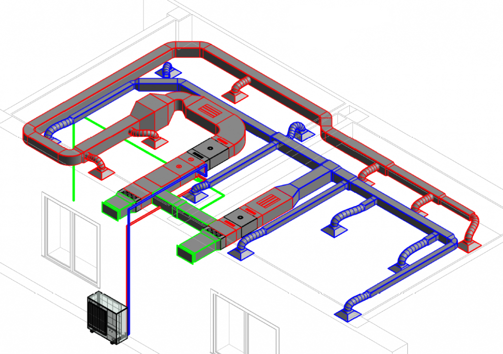
In a traditional HVAC System, Power is not only Consumed by Heat Pump, but also by Fans, Humidifiers, Hydronic Pumps, Actuators, etc.... Heat Pump Manufacturer Data don't account for all of the above, making the prediction of annual Cooling and Heating Energy based on EER or IEER Optimistic and Unrealistic. In large commercial buildings, Annual Power consumption associated with Pumps, Fans, humidifiers, etc... is around 50% of Total annual energy consumption. So when such equipment are missed, calculated annual energy represent half of the real consumption.
Installation Quality
Properly installing and commissioning of any Direct Expansion Machine (whether a Heat Pump or Not) requires time for quality testing. Required tests are the followings: Nitrogen Positive Pressure testing, Negative Pressure Vacuuming, Subcooling and Superheat Adjustments, and other tests.
Most AC technician in Canada and the US charge for the above tests, but they cut corners during their execution. Proper Start-up and commissioning requires at least 48 Hours but most AC technicians install a residential heat pump in less than a day (the average time is 4 to 5 hours).
Proper bending of Refrigerant Copper Pipes
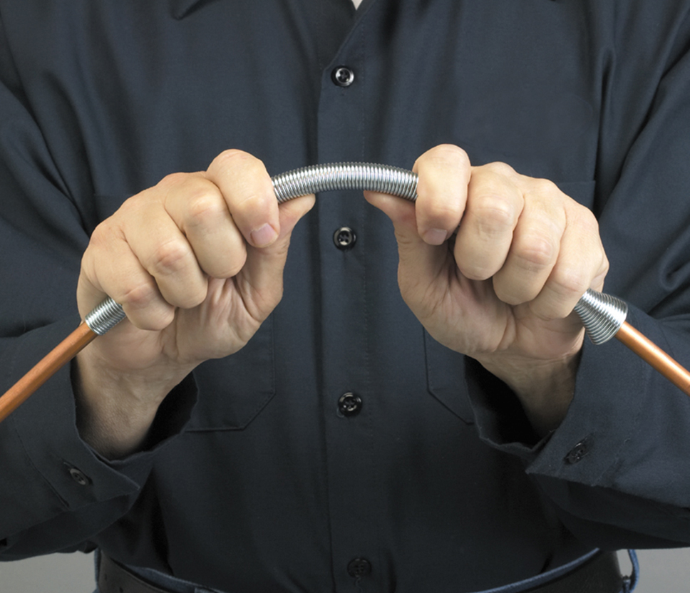

Bending of soft drawn copper pipes could be achieved by using bending springs. Simply place the bending springs over the tubing and bend the spring into the desired shape. The spring will evenly distribute the pressure, preventing the tubing from getting crimped.
Also bending can be done by using the tubing bender. This type of bender facilitates the bending of tubing at precise locations and to the desired angle. Tubing bender is available in sizes ranging from ¼” to more than 7/8”. Bending shall always be done by a professional to avoid kinked bend such as the one in picture on left.
Refrigerant Copper pipes installer shall always favor long radius bends (done by spring bender or pipe bender) over the use of welded 90 or 45 degree elbows. Properly bent pipes have less friction loss, which improves the DX Cooling/Heating machine energy efficiency. Also Long Radius elbows, created by pipe or spring benders, have not soldered to brazed joints which eliminate the probability of refrigerant leakage in the future.
Nitrogen Testing: Positive Pressure Leak Checking
Once all of the installation works has been completed, the system is almost ready to be put into operation. There are, however, a few more important things to be done. One of these is leak-checking the system to ensure that all solder and flare connections in the system were made properly. A leaking air conditioning system will not operate properly and will introduce refrigerant to the atmosphere. Therefore, leak-checking is a must prior to system startup, especially when refrigerant lines will eventually be sealed behind walls or ceilings. Accessing these solder joints will be extremely difficult once the walls and ceilings are finished. The method that will be used on site for performing a leak-check on a system is the standing pressure test:
- The pressure in the refrigerant piping circuit is brought up to approximately 150 psig using dry nitrogen.
- The system is permitted to rest for approximately 5 to 10 minutes.
- The needle on the gauge is marked to indicate its exact position .
- The system is then observed after 12 hours to ensure that the position of the needle has not moved.
- If the needle moves, there is a leak. If it does not, the system is tight and there is no leak.
When the pressure is initially introduced to the system, the manufacturer’s test pressure should never be exceeded. Exceeding these pressures could result in damage to the equipment. The test pressure on a typical indoor unit is approximately 150 psig, so this pressure is safe under most conditions

When bringing the system up for leak-checking purpose, nitrogen is the gas of choice because, after the leak test is complete, it can be safely released into the atmosphere. Small amount of refrigerant can be introduced along with the nitrogen to aid in the location of system leak if one exists.
After the pressure has been introduced to the system, good field practice requires letting the system stand for a short period of time. This gives the gas time to settle and will ensure that the pressure in the system will not change due to this settling. Once the gas has settled, the face of the gauge should be marked, indicating the exact position of the needle. By marking the gauge, any small movements in the needle’s position will be easy to spot.
After the gauge has been marked, the system should be observed later to see if the needle has moved. The time that should be allowed to elapse is 12 hours. if a large leak is present, the pressure in the system will begin to drop rapidly. Smaller leaks, however, may require much more time to show up on the gauge. If the pressure drops over time, a leak exists in the system. In this case, the solder and flare joints, if any, should be carefully inspected.
A liquid bubble type leak-detection solution should be used. This solution shall be applied to all solder joints as well as to all flare connections and Shraeder Valve stems. The formation of bubbles on the surface of the piping indicates the presence of a leak; large bubbles indicate a small leak.
Refrigerant Lines Vacuuming (System Evacuation)

Before refrigerant is added, the system must be properly evacuated. Evacuation is the process by which the pressure in a closed system is reduced, causing any moisture to boil off into a vapor. This vapor is removed from the system via the vacuum pump.
When evacuating a system, the technician should: Make certain that the system is evacuated from both the high and low pressure side and that the vacuum pump is sized correctly for the system being evacuated, Change the vacuum pump oil frequently, Apply heat to the system to speed the evacuation process, Never operate a compressor while a system is in a deep vacuum, Use the largest valve ports possible to speed the evacuation process.
When the system is being evacuated and a vacuum is being pulled on the system, the reading on the gauge manifold will register values below 0 psig. The low side gauge will indicate a reading in the vacuum range from 0” Hg to 30” Hg. The high side needle will indicate a point lower than 0 psig as well, but this value can not be determined because there are no makings on the high side gauge in the vacuum region.
As the pressure in the system approaches a deep vacuum, close to 30” Hg, the reading on a compound gauge becomes less accurate and reliable. For this reason, vacuums are best measured in units called microns. The micron is the unit of linear measurement equal to 1/25,400 of an inch. It represents a measurement above an absolute pressure of zero, which represents a perfect vacuum of 29.92” Hg.
As the pressure in a system is reduced, the vacuum increases. At a gauge pressure of 28.9” Hg, the equivalent reading on a micron is 25,400.00 microns. The micron gauge (Fig A-36) is a test instrument that is designed to measure the vacuum in a system in microns, as opposed to inches of mercury. As the vacuum is increased to 29.8” Hg, the micron gauge will read approximately 250 microns. In a vacuum of 29.92” Hg, the micron gauge will read approximately 25 microns (perfect Vacuum).
Evaporator Superheat and Condenser Sub-Cooling

Evaporator Superheat
On systems operating with thermostatic expansion valves (which is our case), evaporator superheat shall be in the range of 12 to 20º F.
An evaporator superheat well below 12º F is an indication that the system may be overcharged.
An excessively high superheat indicates that the system may be undercharged. Improper superheat can also be caused by other system problems such as reduced evaporator air flow.
To calculate the amount of sub-cooling that a condenser is operating with, two pieces of information are needed: condenser outlet temperature and - The condenser saturation temperature.
To calculate the condenser subcooling, we subtract the condenser outlet temperature from the condenser saturation temperature. Condenser subcooling should ideally be in the range of 10 to 20º F.
High subcooling is an indication that the system is overcharged, and low subcooling indicates that the system is undercharged.
Should the condenser coil become blocked or the condenser fan motor become inoperable, the refrigerant in the condenser coil will not be able to condense effectively, causing the subcooling measurement to drop below acceptable levels.
Choice of heat Pump Type for the application
There are various combination of technologies defining the heat pump market. From Water to Air Cooled, Air/Air to Air/Water, Suitability and Annual performance and energy consumption are not the same.
For applications where distance between Energy Production (Heat Pump) and energy consumption (Air Handling Unit, Furnace, Split, etc...) is not very significant, Air to Air heat pumps are the most logical choice having the highest quality/price ratio.
But for cases where distance between Energy Production (Heat Pump) and energy consumption (Air Handling Unit, Furnace, Split, etc...) is significant, the choice should go for Air to Water Heat Pumps since the cost of pumping water at long distances is lower than the cost of pumping air or refrigerant.


Jenese Delka
Lucille Fernandez
Brylee Hall